I am the Duke of Knurl
June 6th, 2014Real Men Have Aluminum Dandruff
I’m having a lot of fun making parts for my CNC mini-lathe.
Earlier in the week, I made part of a motor mount. It will hold a stepper motor which turns the cross-slide feed. Well, it WOULD have held it. But I made a little booboo. The plans called for a part 3/4″ thick, 2.75″ long, and 2.5″ wide, and somehow, I got the idea that I was supposed to make it from 1/2″ aluminum plate. The part is now a paperweight. The way I’m holding it in the vise is wrong, but it worked.
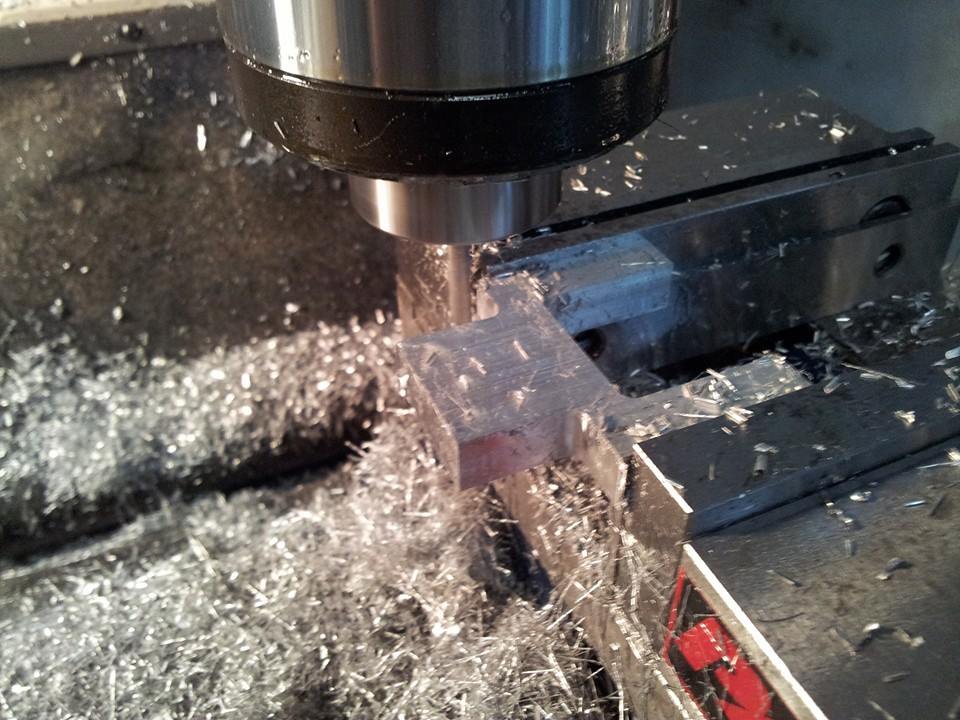
I was very careful when I made this thing. I got it within a thousandth of nominal size, or whatever it’s called. I stepped up my measuring game in order to get there. It’s a PRECISION paperweight.
When I started machining, I watched a lot of videos. I didn’t have machinist buddies who could teach me, and the videos are very informative. In particular, I like the ones from Lex Liberato of Swarf Rat. But they have their flaws. For one thing, most of the guys I watched tended to rely on dial calipers, which are not very accurate.
A dial caliper is an improved (arguably) version of the old vernier calipers we used to use in lab classes. Instead of making your eyes hurt from trying to read tiny vernier scales, they have dials attached to them, and they read in thousandths of an inch (imperial calipers only).
It’s easy to get the idea that this means you can measure something to within a thousandth of an inch of its actual size. That’s wrong.
Back when I taught physics labs at the University of Texas, we were told to tell students to try to estimate down to one-half of the length of the smallest unit an instrument measured. For example, if you had a ruler marked in millimeters, you would try to make a good guess and come up with a measurement accurate to half a millimeter. That won’t work with dial calipers, because their accuracy is actually lower than the smallest unit measured.
Calipers flex a lot, and you can screw up the measurement by applying the wrong amount of pressure. They have little knobs that tighten the jaws against the work, but no one with any skill actually uses the knobs, because they kill accuracy. In reality, you’re supposed to put your finger and thumb on the jaws and push them together. There are a lot of problems with calipers, and a very skilled machinist told me never to use them unless I was satisfied with up to 0.005″ of error.
What you really want are micrometers. Calipers are faster and easier to use, so they’re great for interim measurements when you’re working fast, but when you get close to final dimensions, you want something better. Micrometers will get you within half a thousandth when used badly. If you use them well, you can get down into the low tenths.
Cheap mikes are much better than they used to be. I just got some from Shars, and I paid around $20 each. I checked them using shop-grade Enco gage blocks, and the figures I got (with bad technique) were 0.0003″ off nominal size. Micrometers come with ground carbide doodads that you are supposed to use to measure accuracy, but they can’t be trusted, so don’t use them. Even lame gage blocks will be within a tenth of nominal size. It sounds crazy to say cheap gage blocks are better than carbide standards, but it’s true. Don’t ask me why.
I took out my new Chinese mikes and put them to work on the part I was making, and I came within half a thousandth. I think. Actually, I guess it could be a little more, since I was getting 0.0003″ of error on the gage blocks. Anyway, the parts were very close to specified size. Much closer than they needed to be. Had I been off by fifteen thousandths, it would not have mattered.
I made this Y-shaped mount thing, and I felt pretty smug. Then I saw that I was supposed to drill a 1/2″-wide hole down the center of it. This is the subtle clue that alerted me to the fact that the part was too thin. So today I had to make a new piece of aluminum so I could redo the part.
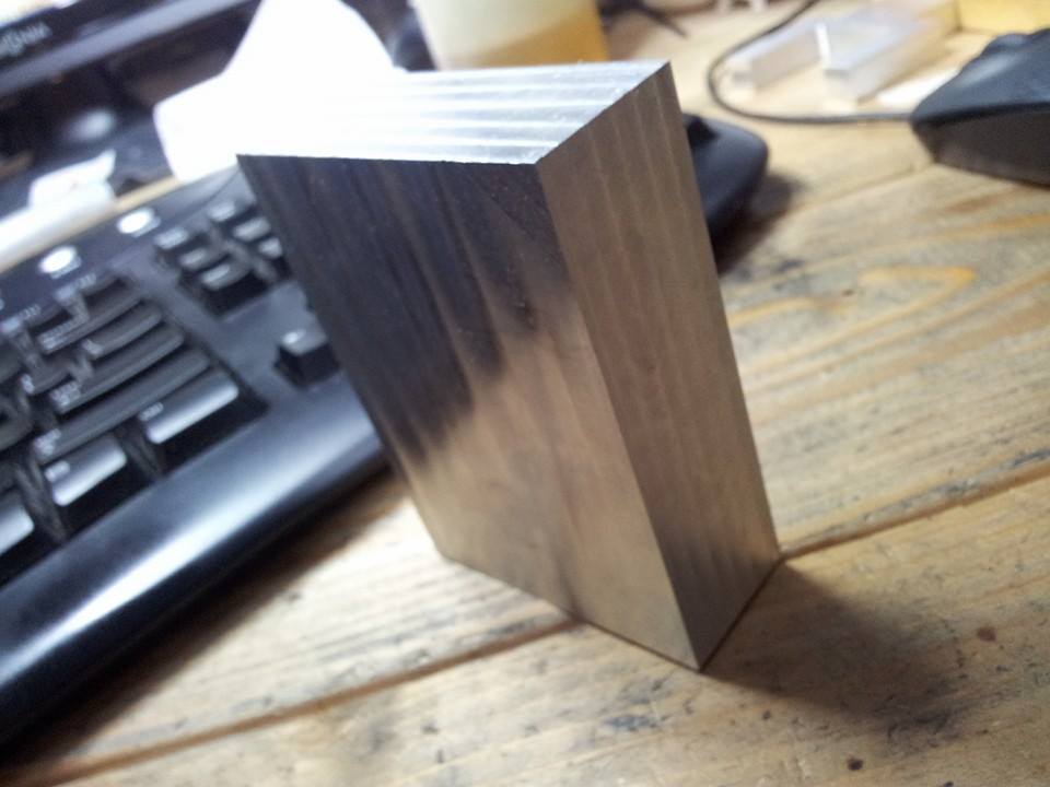
I used my table saw to cut a 1″ slice out of a square aluminum rod 3.5″ on a side. Does that sound crazy? It works. I would not cut steel with it, but aluminum cuts beautifully on a table saw, if you go very slowly and use lots of WD40. In five minutes, you can cut something that would take 15 on a little band saw, and you can get accuracy within 5 thousandths.
I never trust the sides of new stock to be square, so after shortening the block to 2.75″, I put it on the mill with a 1/4″ carbide 2-flute cutter and cut a flat side on the top. I put that against the fixed jaw and put a round piece of aluminum between the other jaw and the other side. This allows the flat side to rest firmly on the fixed jaw, to serve as a reference. I made another flat side and ended up doing all four sides.
Now I had a problem. I had four square, flat sides. But I also had two really large sides, perpendicular to the rest, that were neither flat nor parallel. They had saw marks on them. How do you fix a thing like that? You can’t rest it on parallels and mill the upper side, because it won’t rest flat on the parallels. If you put two flat sides against the vise jaws, it will be level in one direction, but it can slope from one side of the vise to the other.
This really bugged me. Finally, I put two flat sides against the vise, snugged it up a little, and bopped it into line with a wooden brush handle. I put a test indicator on the mill spindle with an Indicol holder, and I moved the knee up and down, measuring how far a flat side veered off vertical. I figured that if a side were perfectly vertical, the block had to be positioned correctly. I got it to where it barely moved.
I put a 1/2″ cutter in the mill and took about 0.020″ off the top of the block. I flipped it over, put it on parallels, and did the other side. Then I checked the thickness, which was uniform. I was too lazy to get out the Indicol holder again or use some other method to check squareness, so I put a machinist’s square up against every corner I could find, and I could not see daylight. Good enough.
The big lessons I learned over the last month were:
1. Calipers are useless for accuracy below 0.005″, in spite of what people claim about their results.
2. Cheap micrometers are good to under a thousandth. Good ones will get you down close to a tenth, if you have good technique.
3. When buying micrometers, you have to check them using gage blocks, because carbide standards are junk.
4. If you test a micrometer, you have to test it at several settings, because a micrometer which is accurate down near 1″ may be less accurate near 2″.
5. Expensive calipers are a complete waste of money, because they’re still not accurate.
6. Don’t use micrometer ratchets, because they’re not reliable. Learn to tighten them directly, going by feel. This takes practice. Which I haven’t done yet.
I also learned some stuff about lathes. Mainly this: don’t use lube when cutting aluminum with carbide. At least not until you do a finish cut. In my experience, it seems to help the finish a little, but that could be my imagination. I’ve used a lot of WD40. It made a big mess. It was completely unnecessary. Thank God it evaporates, or the garage would be full of it.
Milling lessons I learned: don’t use lube when milling steel with carbide. It stinks and doesn’t really do anything.
None of this stuff applies to steel cutters, and you absolutely must use lube when milling aluminum with carbide, because it will weld itself to the cutter. If you screw up and fill your flutes with aluminum, you can knock it out with a center punch. The punch will catch in the aluminum, and this will keep it from going sideways into the sharpened edge of the mill when you hit it with a hammer. You can also soak it in lye to dissolve the aluminum, but some people think this leaves tiny cracks in the carbide which will make it more likely to break.
While I’m sharing lifesaving information, let me tell you about knurling.
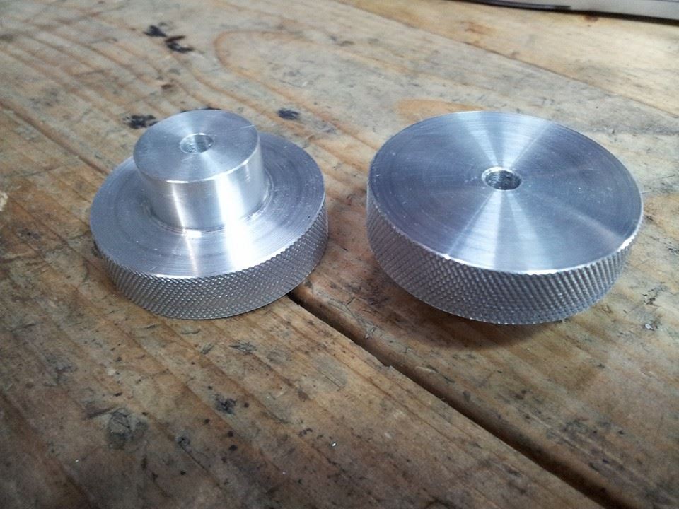
I had to make these knobs for the CNC lathe. They’re 2″ wide, and the narrow part is 1/2″ long and 1″ wide. They’re harder to make than you think.
When you knurl, it’s hard to turn the part. The knurls put a lot of pressure on it, so you need to be able to grip it well. How do you do that with a part like the ones I made? If you make the short part and wide part first, and then you knurl the wide part, you have to hold it by a half-inch-long stub. That’s no good. It may spin in the chuck. If you make the whole thing 2″ wide and knurl one end, planning to cut the stub later, how do you hold the part while you cut the stub into it? You can’t, because you’ll have to put the knurled portion into the chuck. That will damage it, although in practice, you can do it with a level of marring which is nearly imperceptible.
Here’s the answer: soft jaws. These are sacrificial non-hardened steel jaws that replace the hardened jaws of your chuck. To hold a part, you run a boring bar into the jaws and make a bore exactly the size of the part. Then when you tighten the jaws on the part, a lot of metal is in contact with it, so you don’t get pressure points that mar the work. You can make soft jaws yourself, but you have to be stupid to do that, because Shars sells them for about twenty bucks.
I don’t have soft jaws. I made the knobs with a knurled portion about an inch long. Then I put the stubs in the vise and turned the knobs carefully, cutting them down to 1/2″ in width. It’s slow and not all that professional, but it works.
You will notice a shimmery sort of line that runs around the knurls. I’ll tell you the reason for that.
I have a scissor knurling tool. The advantage of this is that it squeezes the part from the top and bottom, applying no net sideways force to it. A scissors tool won’t push the part out of the chuck. It’s great. Buy one.
There is a problem with a scissors tool. You can’t gradually increase the pressure, the way you can with a tool that pushes from the side. You have to adjust it in steps, using a nut on top of the tool. The problem with this is that it’s easy to end up with too much pressure. That’s what happened to me.
When you use too much pressure, as you move the tool down the work, it may turn slightly in the toolpost. When that happens, you get that little shimmery band. It’s a very minimal defect. But you don’t want it, so don’t be afraid to make several light passes.
Here’s another great thing to know: you do NOT have to measure the diameter of the work before applying diamond knurls. I had been taught that this was necessary, but that’s wrong. You have to do it with straight knurls, or they won’t mesh on successive turns. But diamond knurls will work on any diameter. Try it and see.
Also, it’s nearly impossible to get a knurled part with a precise specified diameter, because knurling makes the diameter bigger.
I plan to redo these knobs, but with all the false starts and scrapped parts, I considered these adequate for a 1.0 version.
In the past, I tended to do a lot of machining that required little precision. I called it “woodworking with machine tools.” But eventually, you have to get it together. The last couple of weeks have improved my skills a great deal. I hope the things I’ve told you in this blog entry will help you. Believe it or not, it took a lot of practice, reading, and forum begging to get this information.
Og from Neanderpundit may come over and obliterate all of it, but it has worked for me, and I got it from people who are much better at machining than I am. It may not be the best advice available, but it’s pretty good.
June 8th, 2014 at 10:57 PM
Calipers are for rough on the fly measurement. Calipers are more than adequate for making one off parts, but a mike is really the last word.
Rachet/spring tension thimbles on mikes are there so the big gorilla and the 97 lb weakling will get the same measurement. You adjust the mike so it reads perfectly with only thimble pressure, and you’re on all the time.
The only real way to learn this stuff is to do it. It helps to have a real knee mill and a real lathe.
Chinese mikes are pretty good these days. Trick is to make sure the mike surfaces are parallel- calibrators use an optical flat, close the mike on it,. and examine the interference pattern under a special lamp. Micrometer faces should be parallel within one wavelength of light, and you should never store a mike with the anvils touching one another.
Mike standards are hard to use, and they aren’t always the “Nominal” length. So you etch the actual length on them, and if your mike reads whatever the value of the mike standard is, you’re ok. Mine are, in order, 1.004, 1.996, 3.0005, and 4.0015. For critical measurments the mikes have to be at the temperature of the workpiece and I tend not to touch them with my bare hands when measuring something critical. Some of the Chinese mikes now have insulating plastic blocks on them so the heat from your hands doesn’t cause them to grow.
The more you do the better you will get.