The Unlikely Smell of Success
August 3rd, 2014Lathe Debut Imminent
I’m not at church today because the A/C blew out. I can’t wait until we have our own building.
The CNC mini-lathe is pretty much done. I have to get the electronics going, but apart from adjustments and nonessentials, the hardware is ready to go.
I will not criticize this design, because I am not competent to do so, but I have had some negative comments from experienced CNCers. They don’t like the direct couplings between the steppers and screws, and one said it was a bad idea to use a lead screw to move the saddle. I don’t know what else you would use, though.
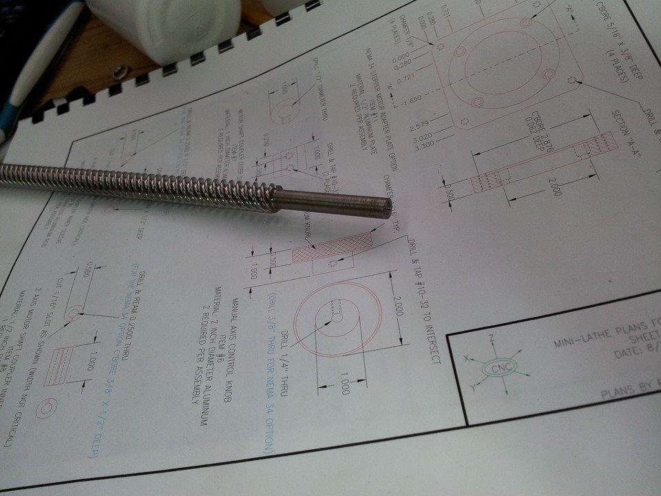
Yesterday I cut the lead screw to size. It had to be 22″ long, with a 1.75″ portion turned down to 0.25″ to receive an adjustable collar. I got it to about 0.248″.
Turning a lead screw in a lathe is pretty nerve-wracking. If you simply stick it in the chuck, you risk ruining the threads. You can bore soft jaws out so they hold it without marring, or you can make a split bushing that goes over it. You chuck the bushing, and it tightens around the screw without harming it.
I made bushings, but in practice, they were no good. When I chucked the screw, it wobbled pretty badly. I considered boring my soft jaws, but I wasn’t sure I wanted to bore all the way through a brand new pair. I might need that metal for something else later.
This was not a precision job, and I had extra screw material, so I tried the gonzo approach. I wrapped the screw in several layers of foil and chucked it.
It’s hard to put an indicator on a coarse thread. It will bounce around. I decided to eyeball it. I put something straight next to it and turned it, and I saw no deflection. I knew that put me within a couple of thousandths, which is not far from the best the chuck can do, so I was happy.
I center-drilled the far end, put a live center in it, and turned 1.75″ down to size. No problems. If it’s not perfect, I can’t detect it without instruments, and that’s more than good enough.
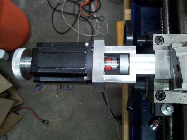
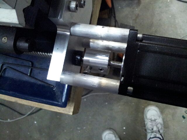
I had a problem when I mounted it on the lathe. I have some new flexible “plum” couplings, and I put one on the z screw. These couplings have an aluminum spider fitting at each end, and in between, there’s a layer of urethane, like a skateboard wheel. They allow for a lot of error in the rotation of the things they connect, but they also pull apart if you pull the ends away from each other. I want my setup to be rigid longitudinally, so the screw isn’t slopping back and forth and creating incredible backlash. I had to go back and use my old rigid connector, which works fine.
Plum couplings are perfect for the x axis, except that the one I got was a tiny bit too long. There was a layer of urethane between the shafts I was connecting, and it was too thick. In order to use it, I would have to make a thicker x mount or alter the coupling. I’ve made the x mount twice already, so my answer was to mill the urethane out. It should not matter. It installed easily, and it looks like it will run fine.
The z screw system goes motor, coupling, screw end, adjustable collar, wave (spring) washer, thrust bearing, mount, thrust bearing, screw body. The collar appears to be there to hold the screw tightly against the mount, putting pressure on the washer and bearings. It has to be very tight. I had problems with it slipping. I had to tighten it to the point where I was afraid the set screw would strip. I don’t know if 0.248″ is too small for the collar or what. When I made the screw, I assumed a couple of thousandths wouldn’t matter. It’s adjustable, right? But it may be that I need to put some foil inside it to take up room. Or maybe I need to make a bigger, tougher collar. In the real world, there would be a taper, I guess, with the bearing pressed onto it so it could not move. But this is not the real world. This is home CNC.
I don’t have a project box, but I have a Bud Portacab on the way. This is a foot-tall lunchbox sort of thing made from aluminum. I want to put plugs on the back for 8 motors (the limit for two Kstep boards). I’m not sure what kind of connectors to use. They have to be 4-wire connectors that will handle up to 18 gauge wire. I will also need a plug for the lathe’s spindle sensor.
I’m getting a lot better at machining, because I have no choice. It’s easy to machine when the plans are in your head, and everything is approximate. When you’re working from drawings, you have to apply yourself.
I’m hoping to see movement from the lathe this week. I need to get it put together and figure Gcode out well enough to do a simple cut. After that, things should get a lot easier. It will just be a matter of study and practice.
Most CNCers don’t do lathes, and that’s understandable. A mill will do a lot more. But I don’t have a mill waiting to be hacked up, and the mini-lathe was sitting here doing nothing. It should be very useful, though, and it will give me some understanding of the most important tool technology of our age. Most people are getting left behind when it comes to CNC/3D printing, and ten years from now, they’ll be like the old geezers who hate cell phones. “Damn this thing. Hello? Hello? What? I have to open it? Hello? Hello? Which button?”
After this, I have to make the lathe ball-cutter for which I bought plans. After that, I might like to make a small surface grinder. I considered making a tool grinder, but they’re not really that useful. People tell me that even if you have a great commercial grinder, you will probably do bad work, because it takes skill. And cutters aren’t that expensive, really. A surface grinder would be nice. If you like making machining accessories, you will want truly flat surfaces once in a while, and hand scraping is a real chore.
Hope I have a victory Youtube to post soon.
August 4th, 2014 at 12:17 PM
You are basically using the servo’s bearings as thrust bearings. It will work but they will wear very quickly and lose accuracy very quickly. The leadscrew should be completely self supporting, and the lovejoy (urethane spider) coupling should work without issue. if the motors are cheap, no biggie. If the motors are expensive, you should find a way to capture the end of the leadscrew. Most motor’s bearings are not designed to take axial thrust otherwise, looks great. .
August 4th, 2014 at 11:09 PM
I thought the collar was there to mash the mount between the collar and screw shoulder, to limit the screw’s movement and prevent it from putting lengthwise pressure on the shaft.
I am afraid I am going to give Googlers the impression that this is a bad design, and they’ll quit buying plans from the guy who sells them. I hope anyone who reads this will realize that I am the weak link in the chain. This design does work. I can think of some things I would like to change, but you can go on Youtube and see this design in action, and it seems to do the job quite well.
The cabinet arrived, and now I have everything I need to make this thing run. I don’t have CAM software, though. I won’t install the demo until I see this thing move. I don’t want to start the demo trial period until the machine is functional.
August 5th, 2014 at 2:19 AM
There probably should be a collar/bearing on both sides. The leadscrew should stay put with no axial play without the servo. Maybe the print isn’t exactly clear, I’d ask the guy for some clarification.
August 5th, 2014 at 12:38 PM
The collar is on the tailstock side. On the headstock side, the 1/4″ end on the screw goes to a 3/8″ shoulder. I believe the hope is that the bearings will be compressed between the shoulder and collar.
I am trying to figure out the best way to get rid of that collar, because I don’t trust it.
It just occurred to me that I could thread the end of the screw and put a nut with a jam nut on it, instead of the collar. But I would have to find some way to make the end of the screw compatible with a coupling. Maybe I could mill it square, make a sleeve with a square hole (rotary broach) to go over it, and put a set screw in the sleeve. I would have to make a cutter for the broach, though. This is starting to sound like work, plus there may be skill involved.
Maybe I should just put a second collar on for insurance. Or a long sleeve with two set screws. That would probably be the simplest answer.
August 5th, 2014 at 9:03 PM
The nut is a good idea, but you can also just make a spacer between the coupling and the thrust bearing, and then secure the coupling with a nut and a washer. That way you only have to thread a little of the shaft. You’ll have to probably cut a recess in the coupling to accommodate the nut on the end of the shaft. Or you could drill an axial hole in the end of the shaft and use a screw, if it’s soft enough to tap.
August 11th, 2014 at 12:28 PM
by the way, Automation Direct is the best place to buy connectors and stuff. This is the kind of connector you put on the end of the cord
http://www.automationdirect.com/adc/Shopping/Catalog/Wiring_Solutions/Multi-Wire_Connectors,_Heavy-Duty_(ZP-MC_Series)/Size_3A_(3,_4,_5,_7_and_12_Terminals)/Single_Lever_Housings_(Size_3A)/ZP-MC03A-2-STE11P
This is the cord grip that clamps on the wire
http://www.automationdirect.com/adc/Shopping/Catalog/Wiring_Solutions/Multi-Wire_Connectors,_Heavy-Duty_(ZP-MC_Series)/Spare_Parts_-a-_Accessories/Plugs,_Adapters_-a-_Cable_Glands/ZP-MC-CG-11P5
This is the connector that goes inside it
http://www.automationdirect.com/adc/Shopping/Catalog/Wiring_Solutions/Multi-Wire_Connectors,_Heavy-Duty_(ZP-MC_Series)/Size_3A_(3,_4,_5,_7_and_12_Terminals)/Inserts_(Size_3A)/ZP-MC03A-1-MS004
This is the mating connector
http://www.automationdirect.com/adc/Shopping/Catalog/Wiring_Solutions/Multi-Wire_Connectors,_Heavy-Duty_(ZP-MC_Series)/Size_3A_(3,_4,_5,_7_and_12_Terminals)/Inserts_(Size_3A)/ZP-MC03A-1-FS004
and this is the part that bolts on the back of your cabinet
http://www.automationdirect.com/adc/Shopping/Catalog/Wiring_Solutions/Multi-Wire_Connectors,_Heavy-Duty_(ZP-MC_Series)/Size_3A_(3,_4,_5,_7_and_12_Terminals)/Single_Lever_Housings_(Size_3A)/ZP-MC03A-2-SBHP
There are a lot of mix and match things that go with this, more terminals per connector, etc. but Automation Direct is the best place to go for this stuff, good quality and inexpensive.
August 12th, 2014 at 10:45 AM
I appreciate those links. That would have been a great setup, but unfortunately, I found out about it after buying audio connectors, soldering them, and drilling the box for them.
It’s funny; people on CNC forums are nearly useless. They have no clue what to use.