Machining Progress for June
June 21st, 2014This Junk Actually Works
I guess people who come here solely to read about God will be sore, but I am here today to talk about machining. I am making progress on the parts for my CNC mini-lathe. You can find and buy the plans at Ron Steele’s site.
In an earlier post, I discussed a mount I was making from aluminum on the mill. If you look at the photo, you can pretty well tell I was milling it from flat aluminum plate. I had a few problems. First I misread the plans and tried to make it from 1/2″ plate. Then I saw that it was supposed to be 3/4″ thick. I started over.
The plans called for a 0.510″ bore down the center of the part, to accommodate the screw that moves the lathe cross-slide. The bore had a shallow 0.625″ counterbore, because the screw has a shoulder on it, and the shoulder fits the counterbore. On either side of the bore, centered 0.411″ away, there was a #18 hole drilled through, and there was also a 0.297″ counterbore in the #18 hole locations, to a depth of 1.1″.
This means there was a big bore through the material, and to either side, there was a 1.1″-deep bore centered 0.411″ away.
If you add up the numbers, you find that when it’s all done, there is roughly 0.010″ of material remaining between the main bore and each counterbore. For all intents and purposes, that’s no metal at all. And when I shoved a homemade counterboring tool in there to make the counterbores, the thin aluminum sagged and distorted. I could have bored it out and not worried about it, but it wasn’t workmanlike, even by my standards. I decided to make a third part.
I measured the lathe for myself. The plans are generic, for lathes sold by Harbor Freight, Grizzly, and so on. My lathe is a Big Dog, made by a Chinese company called Real Bull. It’s slightly different. I don’t know how closely the plans fit the other lathes, but they were way off for mine.
I needed a bore about 0.400″ wide down the middle, and the counterbore on it only had to be 0.510″, so that meant I could have about 0.060″ of metal on either side of the bore, not 0.010″. Great news.
I also realized that the 1.1″ counterbores were not needed. The whole point of the wide counterbores was to admit fat M4 screw heads. The idea was to slide the short screws down into the bores and then through the #18 holes and into the lathe. This would have allowed me to keep the OEM 10 mm screws. Obviously (now), longer screws would permit shorter counterbores. So that knocked about 0.090″ off the depth I would have to bore. Great.
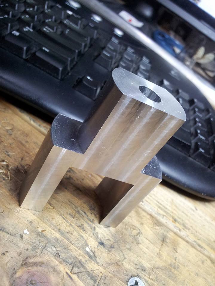
Looking at the part, I realized it was symmetrical about the main bore’s axis. That meant a mill was not the ideal tool. It was made for a lathe. So I bought a 2.75″ round rod and used it instead of plate.
I cut it to 2.25″ in diameter. I trimmed one side down to about 1.350″ in diameter. That gave me a part shaped like a hat. Then I had to put a 1.500″-wide bore in the big end, to a depth of 1.400″. My ability to bore a blind, flat-bottomed hole on the lathe let me down, so I did it on the mill’s rotary table and got gorgeous results. Now I had to put flats on it in order to turn it into a flat part.
The original part was 0.750″ thick. Measuring my lathe, I realized I could make it thicker on one side. That would allow me to rest more metal against the lathe apron, providing more resistance to flexing.

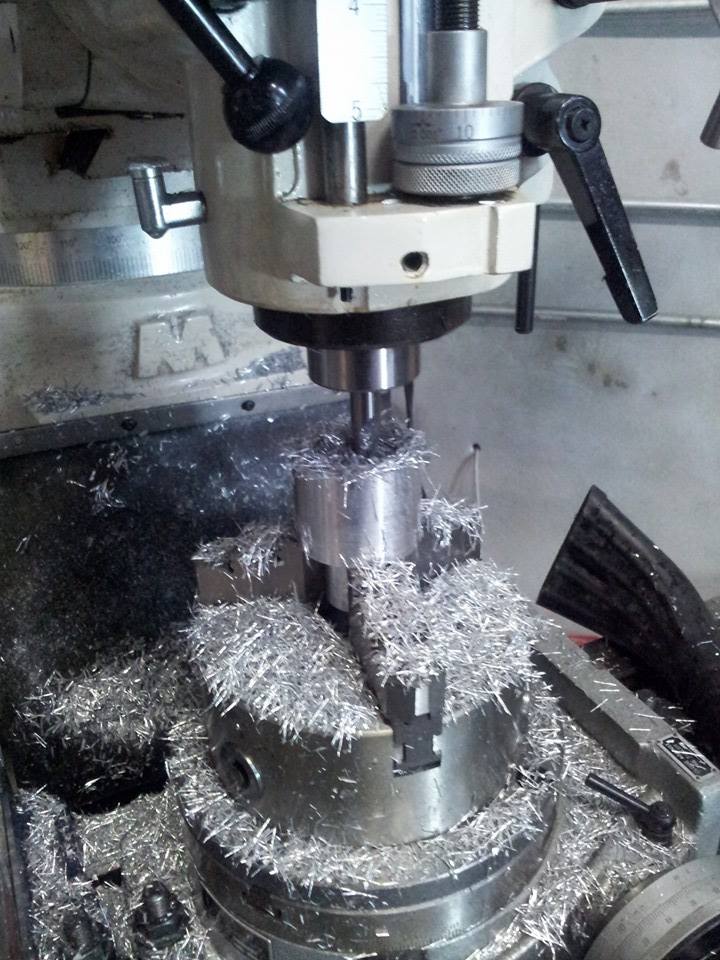
I guess this is dull enough already, so I’ll just put up a photo of the part being cut to size.
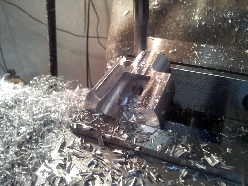
There is nothing under the part in that picture. People suggested parallels, but I just clamped it in the vise and indicated it horizontal to within a thousandth. DONE! Then I flipped it and rested the new flat on parallels. The result was perfect.
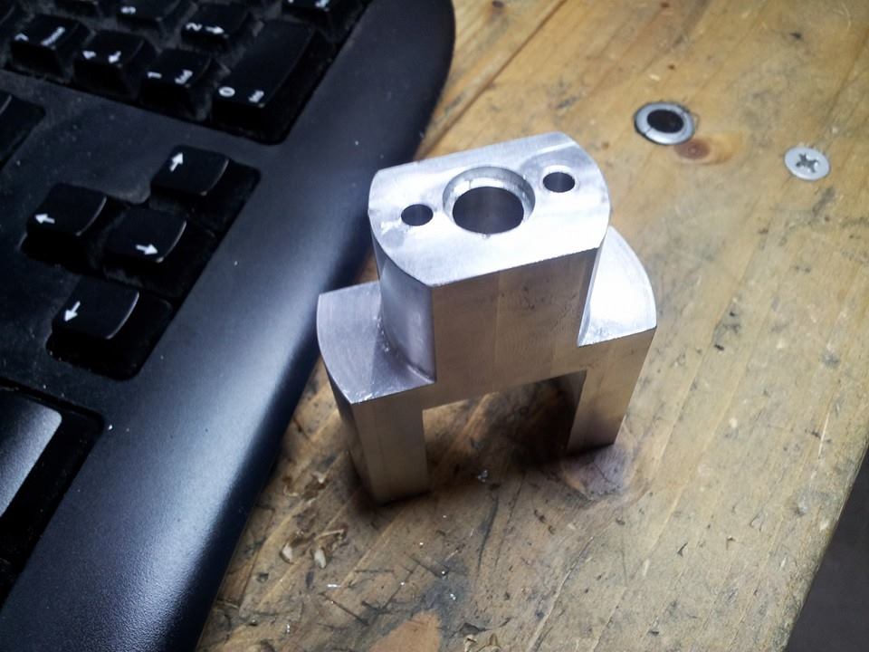
For reasons I no longer recall, I saved the top counterbore for the mill. Not a great idea, but it worked. I used a CDCO co-ax indicator on the main bore, and I got it to within on 0.0005″ tick. That’s crazy, because it was a drilled hole, and drilled holes are not supposed to be that round, but it did work. I opened up the counterbore using a heavy boring head and a cheap brazed carbide boring bar. Then I put the #18 holes in, using a center drill and my new set of cheap Harbor Freight HSS drill bits.
A word about these bits. You need them. It’s a 115-piece set for about $35. People have complained about the points being off-center, and maybe that’s true. The two bits I’ve used cut true, though, and you should be able to fix the bad ones in your set. But there’s more to it than that.
There will be many times when you’ll want to alter a drill bit. I needed a 0.297″ counterboring tool, and I didn’t have one. An expert told me I didn’t want one, because counterboring tools have little pilot doodads that hang off of them, and they snap easily. He said I needed to grind a 19/64″ drill flat on the end. My main drill set is US-made carbide, and I am not going to grind those bits up, because the discount price is over $200. If you have Harbor Freight bits, who cares? Grind away.
Also, cobalt is not ideal for aluminum. I found this out this week. I was drilling slower than I should have, and the bit grabbed and shattered. I think there were five pieces. HSS is less likely to do that in aluminum.
The part is really beautiful now. Much nicer than the one in the plans. In retrospect, I see that I could have done the whole thing from one piece of metal, but I would have had to put it on the rotary table, and with a 3-jaw chuck or a clamping set, that would have been awkward. Which is why I am planning to get rid of that chuck and get a 4-jaw.
My measuring capabilities are getting better, so I am now making parts with very tight tolerances. I realized I had no accurate way of measuring depths, so I decided to get a depth micrometer. The Chinese set from Shars runs over a hundred bucks, but some Ebay guy is selling NOS Scherr-Tumicos for about $62, delivered, and now I have one. It’s beautiful. Unfortunately, to measure different depths, you will have to use internal rods of differing lenghts, and every time you switch, you have to put the mike on a reference surface and calibrate it. If you don’t have a granite surface or something else that has been ground flat, you will have a problem.
Now I have to worry about a coolant system. An Israeli company called Noga makes inexpensive flood systems, but I don’t want one. I think it’s unnecessary. I think I can come up with something that just drips. I have never needed to flood work on the lathe, and in order to do it, I would have to cut up the lathe pan, add a drain, add a pump, add a reservoir, and deal with a gallon or so of dirty coolant. I think I can run a tube under the chip guard and mount something on the cross slide, to follow the part. It can drip WD40 or oil directly on the point of contact. People with mills use a ton of coolant, but I don’t think it’s needed here.
Here is the Alibre drawing I did for the part. For some reason, the screw holes in the bottom of the feet are not visible. Not sure what’s up with that. Some people say you have to create an imaginary plane and drill through it.
Anyway, it’s going well. And I think I’m going to have to have a CNC mill and router in order to feel whole. Not sure about a printer. I think they’re only good for 3D prototypes. I don’t know if that’s worth the money, when you can simply make a part or draw it well. I don’t think the flimsy plastic parts these printers make are very useful yet. Maybe I’m wrong. Sooner or later they’ll print things in metal or something durable, though.
If you have a CNC router, mill, and lathe, you can do a ton of stuff that’s actually useful. In fact, you would probably have to hide it from your neighbors in order to avoid running a free fix-it shop.
I guess I’ll spare everyone the story of how I left a wrench on my drawbar and snapped the shear pins when I turned the mill on, but I will tell you this much: if you have a Bridgeport-type mill, and you obstruct the nut somehow while the motor is running, and it quits working, don’t despair. They’re made to take this. Here are the symptoms that will have you wetting your pants:
1. Cutter continues turning under power.
2. Spindle brake doesn’t work.
3. Drawbar nut turns easily, but drawbar doesn’t tighten or loosen when turned.
Here is what happens. The bar has an upper part, which is hollow, and a lower part, which is just a rod with threads at the bottom. The parts are connected by two perpendicular shear pins which are very soft. When you obstruct the rotation of the nut, these pins may snap. Your mill is not damaged. Just pull the nut part up out of the mill, put a rod down into the top and use it to bonk the top of the bottom half of the drawbar to loosen the collet, and draw the bar out through the spindle opening. Then insert a magnet into the top opening and retrieve the round bushing that came with the drawbar. It will be sitting loose on top of the spindle. You’re done. Now if you want you can hammer new pins into the bar, or you can order one online for about $20, delivered.
Right now my drawbar is held together with a single pin I made from mystery metal. I drilled and punched the remains of the old pins, and I lined the drawbar holes up to hammer new pins in, but after the first one went in, the holes, incredibly, were misaligned, so I gave up on the second pin. I ground off the excess, and I was ready to go. I think things worked out fine, because I don’t know how strong that mystery metal is, and I do NOT want pins that are too strong. Next week the new bar arrives, and I’ll keep this one as a spare.
The accident left a couple of tiny dings in the part, but I’ll get over it.
Sorry I don’t have more photos, but I am not really working hard to document this mess.
I can’t wait to get this thing running, but with all my errors, it could be a while.
June 22nd, 2014 at 7:39 AM
Nicely done.
A CNC mill, an old used one, for instance, is probably your best bet. A Makino KE55 works like a knee mill, and does everything a knee mill will do, but has a CNC control that would cut 90% of the time out of the job you just did.
A CNC lathe is a similar issue, and one of the very best ones is a Harrison Alpha, for the same reasons; cnc controls on a manual machine.
When you get somewhere where you can put up a real shop with real 3 phase power, you will find this a lot easier. Keep your eye protection and closed toed shoes on and keep learning.
June 22nd, 2014 at 6:01 PM
Thanks, Og. I looked up the Makino. That’s pretty hardcore.
I do have 3-phase, via a Phase Perfect, but I would not call this a real shop. I don’t know if a Phase Perfect qualifies as real 3-phase, but it has been a nice convenience.
The guy who sells the plans for the lathe I’m altering says the lathe can still be used manually, but now that I’m working on it, I see that there is a small bug in that theory. There are no graduations on the new knobs.
I guess I could modify the knobs though. I don’t have the tools to do a good job of putting numbers on them, but I could get by with stamps.
June 23rd, 2014 at 11:18 AM
the makino- and machines like it, there are many- are common and not horribly expensive. I know where there is one now you could put your hands on for under ten grand. Real three phase power is more efficient and less expensive.
Once you have the lathe online you will be able to use the computer like a DRO, you won’t need dials on the handles.
June 23rd, 2014 at 11:43 AM
Yesterday I was surprised to find a small CNC mill for sale for $800, with Mach 3, a 4-axis controller, and tooling. It’s really tiny. Based on a Taig. It’s called a Micro Mill DSLS 3000. I am considering buying it because it’s ready to run and comes with software. These things retail for something like $4000.
I thought it would be a nice buy, because I should be able to get my money back out of it, and it would be a cheap way to learn the basics.
June 23rd, 2014 at 3:52 PM
There’s nothing wrong with the taig. mach 3 is simple software to learn and it’s easy to use, but it won’t teach you much about real cnc, because you’ll move up to a real cnc and nothing will be like that at all. What it will allow you to do is make parts, which is great. get a raw lower forging for $20 and machine an AR lower for your own use. The small mill will do the things the big mills will do, you just won’t be able to take big cuts without a lot of vibration and nastiness. but with CNC, you can set it up to take small passes, remove .005″ of material at a time, and sit and read a book for ten hours while it cuts.
June 25th, 2014 at 6:25 AM
What software are you using for designing your items? Is the machine capable of importing different formats i.e. Autocad, 3DS Max, etc?
June 25th, 2014 at 12:21 PM
I’m using Alibre Design. I got a deal on it. I don’t have the slightest idea what it can import or export, but I’m sure their website will tell you. The new name is Geomagic.
June 27th, 2014 at 1:15 PM
Alibre can open IGES files and I think Step files. it can save to DXF format (2d) but if you download Draftsight, which is totally free, you can do all the 2d you want, it acts just like AutoCAD, and it will open edit and save native AutoCAD files. For 2d it’s hard to beat, but it will not do 3d. I’m glad you decided to go with Alibre- it’s not as powerful as some other 3d software but it’s pretty darn good, and the price certainly cannot be beat.